Demonstration Video
Introduction
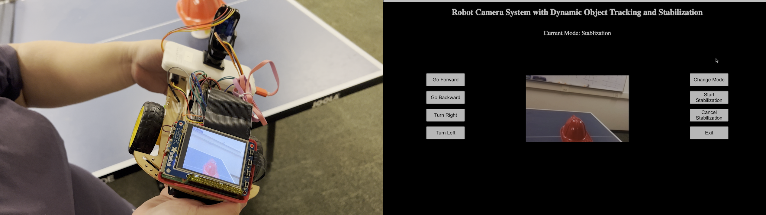
The Robot Camera System is an innovative project that combines robotics, computer vision, and web technology to deliver a dynamic and user-friendly experience. Utilizing a Raspberry Pi 4 board, Pi camera, BNO055 orientation sensor, and a mobile robot car, this system offers two modes of operation: handheld and remote control. In the handheld mode, the user navigates via a PiTFT screen and physical buttons, choosing from manual control, object tracking, and stabilization modes. The remote mode, accessible via a Flask-built web interface, offers the same operational modes plus the ability to control the robot car's movement.
Despite the operational mode chosen, the system ensures a consistent user experience through seamless data and command sharing between the PiTFT screen and the web interface. This project demonstrates a unique blend of modern technologies, offering an intelligent camera system that can be operated directly or remotely. Further sections will detail the project's architecture, functionalities, and codebase.
Project Objective
This project is grounded in several key objectives that drive its design and implementation. These objectives can be classified into primary and secondary goals, depending on their direct impact on the project's overall success.
Primary Objectives:
- Interactivity: This project aims to provide an intuitive and interactive experience for the user, whether they are directly operating the system via the PiTFT screen and physical buttons or controlling it remotely through the web interface.
- Dynamic Object Tracking: An essential goal of this project is to implement robust and real-time object tracking, allowing the camera to follow a selected Region of Interest (ROI) seamlessly, irrespective of its movement.
- Stabilization: The project targets achieving superior image stabilization, ensuring that the camera frame remains horizontal despite any rotation of the camera or the robot along the roll axis.
- Remote Control: A significant objective is to build a responsive and user-friendly web interface, enabling the user to operate the system remotely, including controlling the movement of the robot car.
Secondary Objectives:
- Integration: While not a primary goal, ensuring seamless integration between the PiTFT screen and the web interface is a secondary objective. This will allow for a consistent user experience and smooth switching between the two modes of operation.
- Resource Management: Proper resource management, including graceful exit and cleanup of system resources, is another secondary objective. While it may not directly affect the system's functionalities, it is crucial for the system's robustness and longevity.
- Documentation: Providing clear and comprehensive documentation is an objective that underpins the project's usability and maintainability. This includes not just user manuals, but also well-commented code and system design documentation.

Design and Testing
The project's development involved several design steps, each representing different stages of the project. Each phase was thoroughly tested to ensure the integrity of the functionalities and overall robustness of the system.
Design Steps:
1.Requirement Analysis and System Design: In this phase, we gathered and analyzed the project requirements to establish a clear understanding of the system's objectives. We identified the key components of the system, including the camera module, the Raspberry Pi, the PiTFT screen, an IMU, the robot car, and the web interface. The system design involves different operating modes, which are manual, object tracking, and stabilization. A high-level system architecture was designed, which illustrated the interaction between these components, as well as the overall system flow.
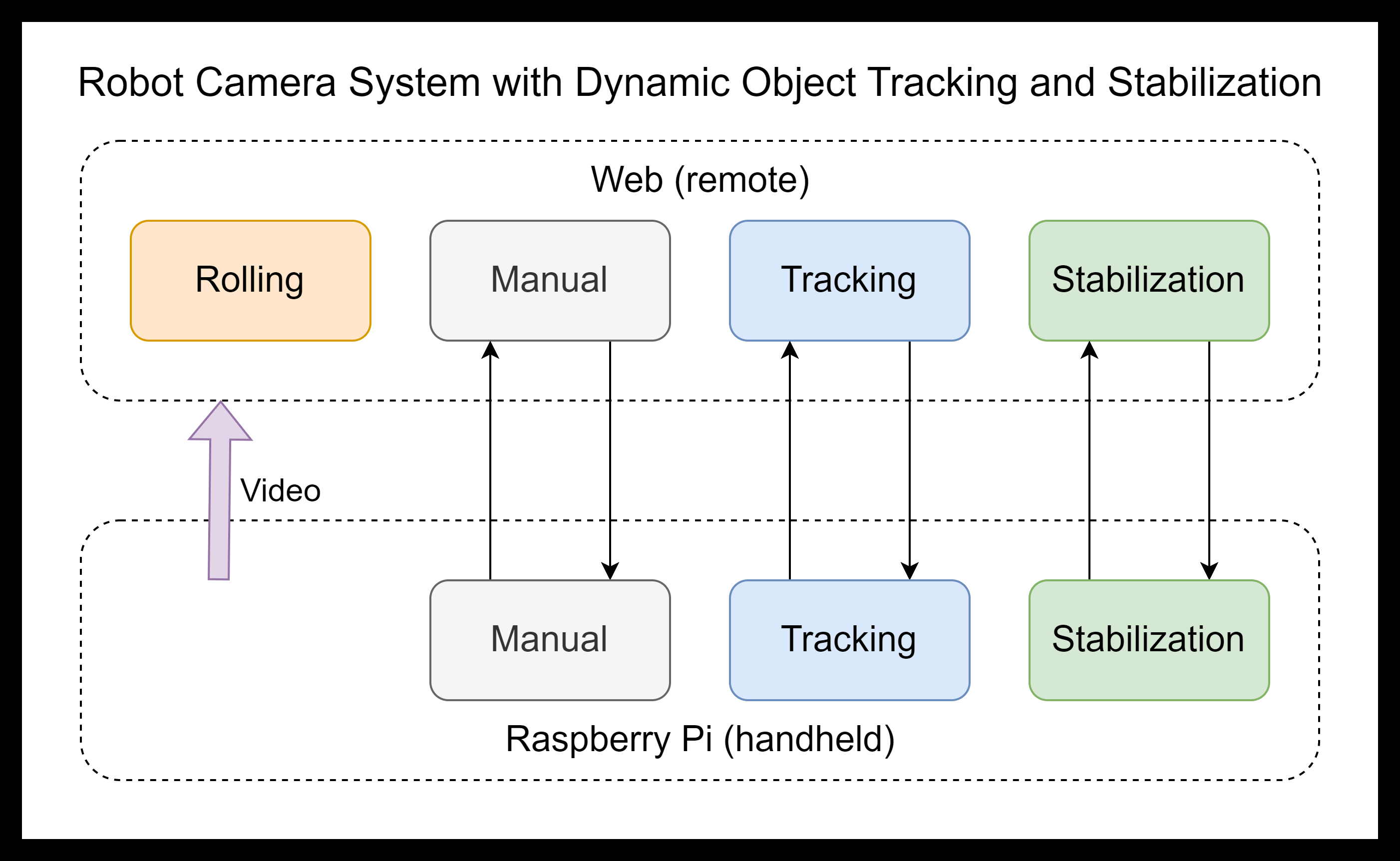
2.Development of User Interface: The user interface for our system was developed with a dual-approach strategy, offering users the ability to interact with the system both locally and remotely.
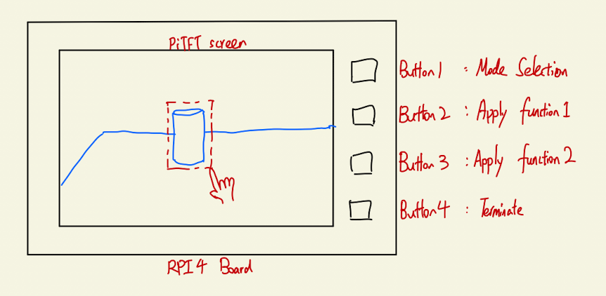
a.PiTFT screen interface: For local operation, we integrated a 2.8-inch PiTFT touch screen into our system. This interface is designed to be user-friendly, providing real-time feedback and control over the system's state. The screen displays the video feed from the Pi Camera and allows users to interact directly with the system. To program the local interface, we used a combination of Pygame and OpenCV libraries. Pygame helped us create an interactive graphical interface, while OpenCV was used to process and display the camera feed. The ui.py script provides different modes of interaction. For instance, users can manually control the camera via mouse movements or input coordinates directly. The update_screen.py script is responsible for refreshing the display with the latest camera frame and any overlay messages. The script can handle dynamic changes, such as rotating and cropping the frame based on roll error, converting the frame to the correct color format for Pygame, and overlaying messages over the frame.
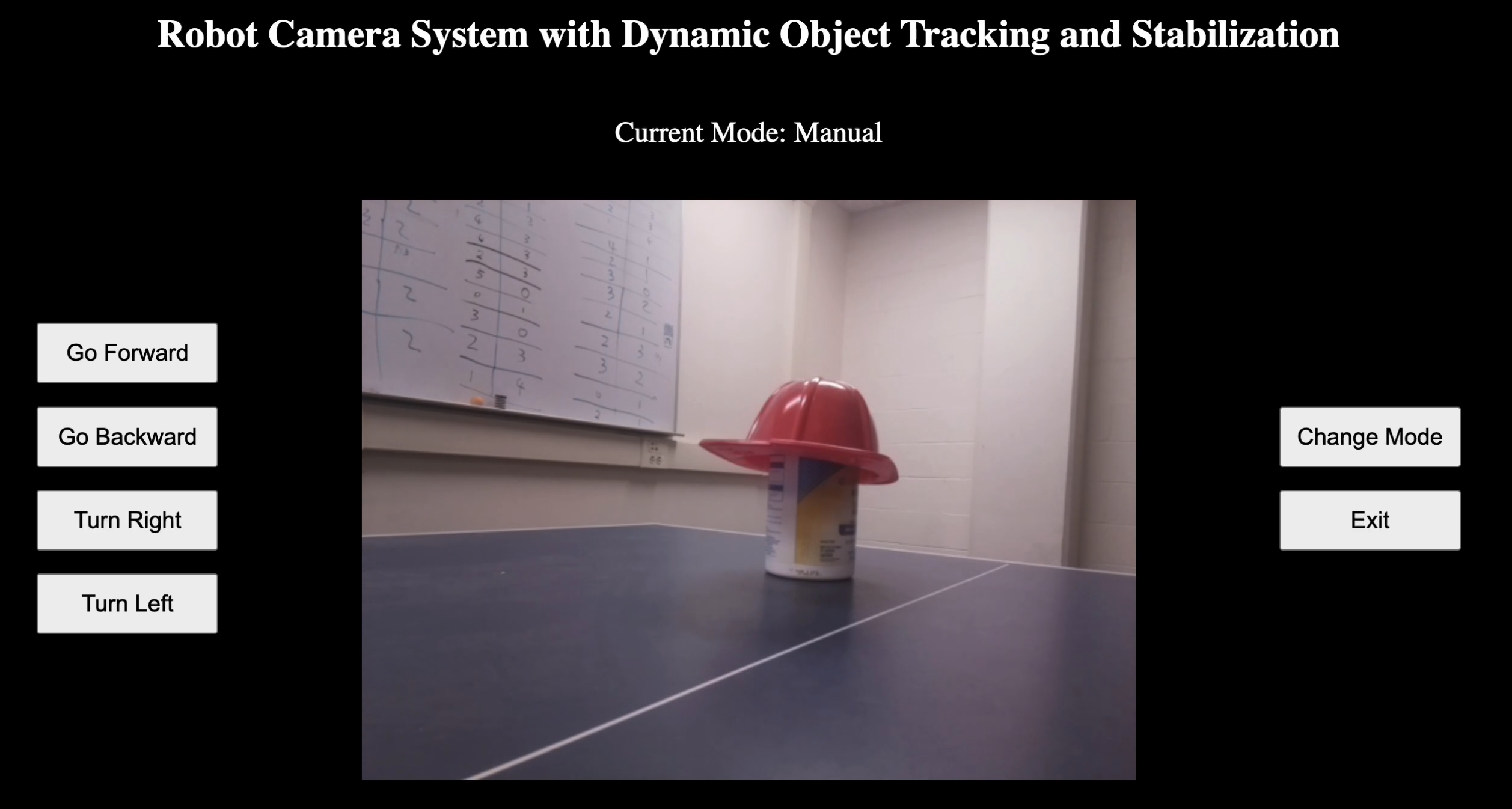
b.Web Interface: To allow remote operation, we developed a web interface using Flask, a Python micro web framework. This interface replicates the functionality of the local interface and adds remote control capabilities. The web.py script sets up a Flask server, providing endpoints for a video feed, button clicks, mode changes, and rolling control. The video feed displays the camera view, while the buttons enable pausing/resuming tracking and setting coordinates manually. Rolling control allows the car to move in different directions. The car's mode can also be changed, affecting its behavior. The web interface allows users to interact with the system from any device with a browser, offering a convenient way to control the robot car remotely.
Both local and web interfaces are designed to be intuitive and user-friendly, offering the same control options and feedback to users.
3.Object Tracking and Stabilization: This phase was crucial in ensuring a stable and clear video feed for the user, even when the robot car was in motion. It was split into two major sections:
a.Object Tracking: We implemented object tracking using the Minimum Output Sum of Squared Error (MOSSE) tracking algorithm. This method is known for its speed and robustness against variations in lighting, scale, and in-plane rotation. It works by creating a model of the object or region of interest (ROI) selected by the user, then updating the model frame by frame to follow the ROI throughout the video feed. The user could select an object or region in the camera feed through either the PiTFT screen or the web interface.
b.Video Stabilization: To prevent the video feed from appearing shaky when the robot car was moving, we implemented a video stabilization system based on readings from the BNO055 Absolute Orientation Sensor. This sensor provides accurate orientation data in 3D space, which we used to calculate the camera's movement and adjust the video feed accordingly. We used a digital gimbal system that adjusted the video frames based on the sensor data to counteract the camera's movements and stabilize the video feed. This ensured a smooth and clear video feed, enhancing the user experience.
4.Robot Movement Control: The robot's movement was controlled using a web interface, which provided two methods for the user to control the robot: either by clicking buttons on the web interface or by using the keyboard. The underlying software was implemented in Python, using the RPi.GPIO module to interact with the Raspberry Pi's General Purpose Input/Output (GPIO) pins, which controlled the motors driving the robot.
a.Initialization: In the initialization process, the robot's motion control pins were set to their correct modes and initialized to a LOW state, effectively stopping any movement. A Pulse Width Modulation (PWM) signal, which is used to control the speed of the motors, was also set up on one of the GPIO pins.
b.Movement: To move the robot forward, the GPIO pins controlling the forward direction of the robot's motors were set to HIGH, while the pins controlling the backward direction were set to LOW. This configuration was reversed for moving the robot backward. For rightward movement, the GPIO pin controlling the right direction was set to HIGH, and the pin controlling the left direction was set to LOW. This configuration was reversed for moving the robot to the left.
c.PWM Control: The robot's speed was controlled using a PWM signal. Different duty cycles were used for different movements to provide a smoother user experience. To stop the robot, all the GPIO pins controlling its movement were set to LOW, and the PWM signal was stopped.
The movement commands could be issued either by clicking the corresponding buttons on the web interface or by pressing the corresponding keys on the keyboard. This provided a flexible and intuitive way for the user to control the robot.
5.System Integration: With all components developed individually, we integrated them into a cohesive system. This process involved:
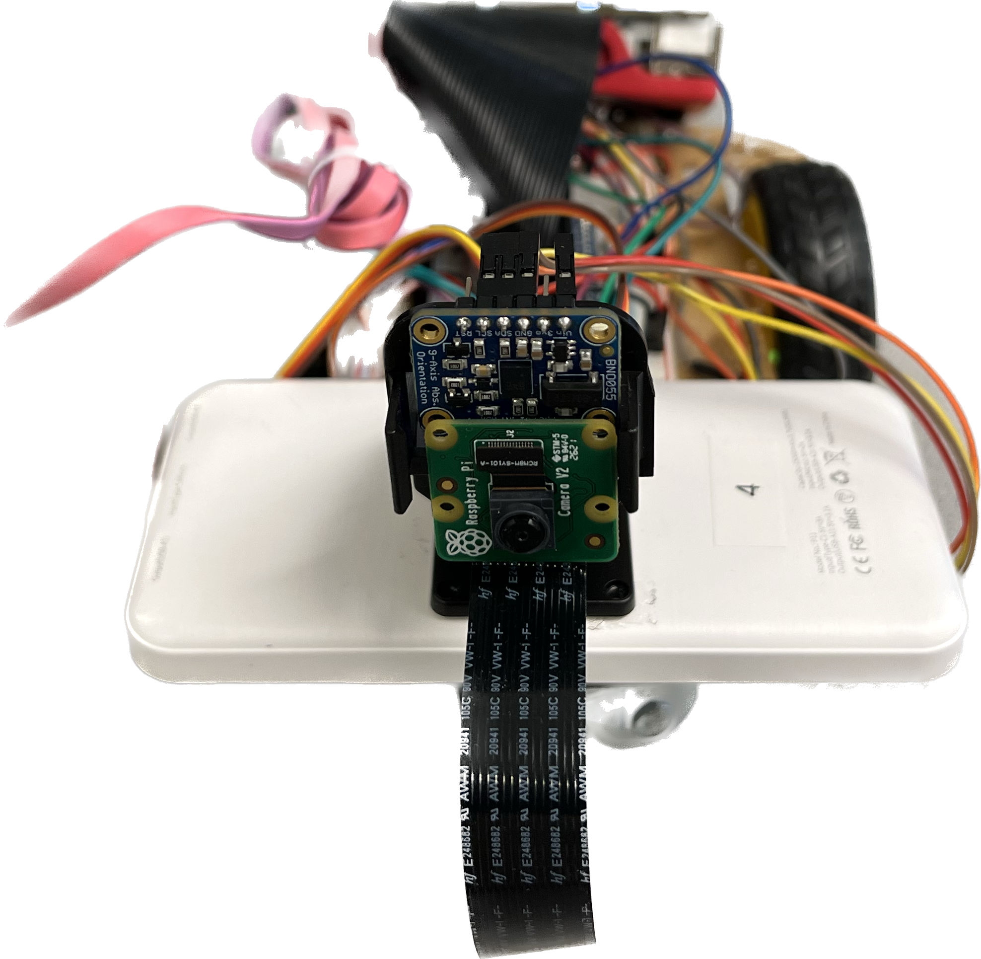
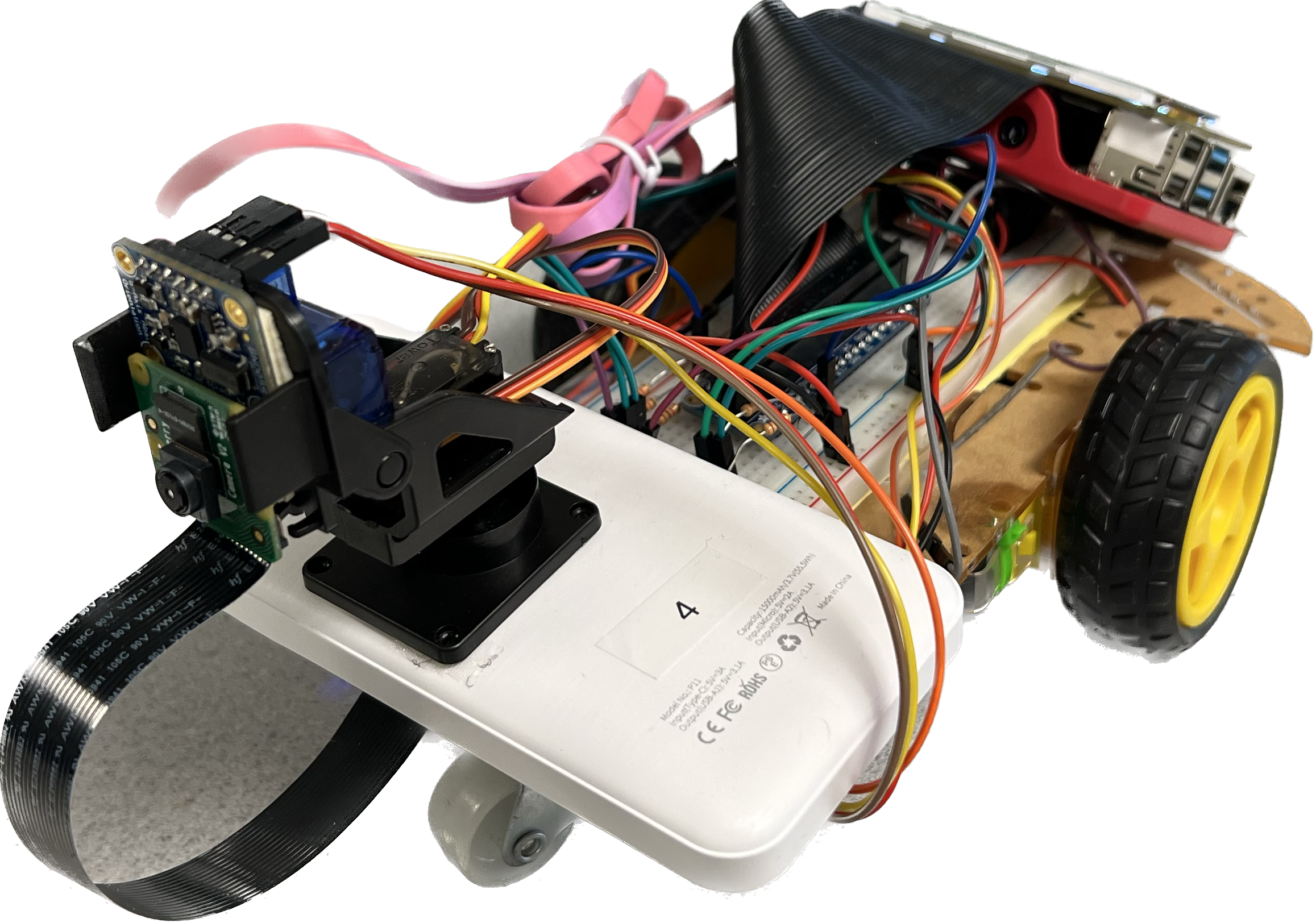
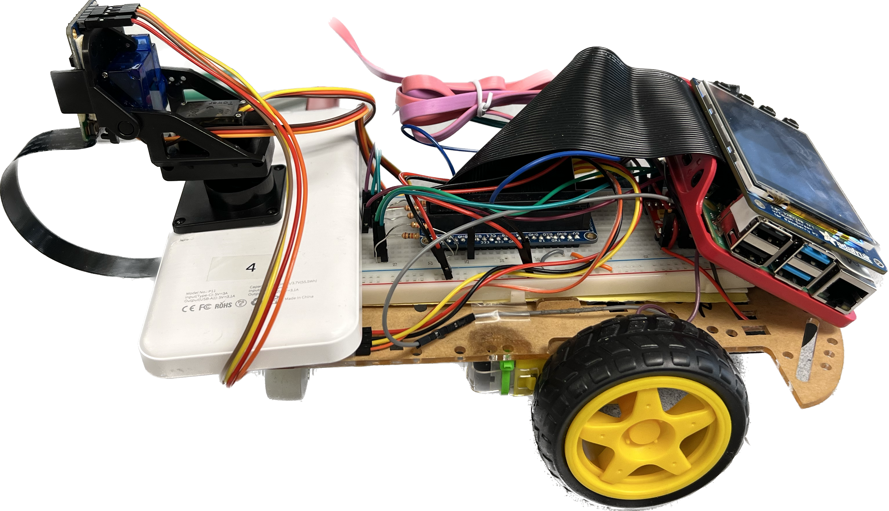
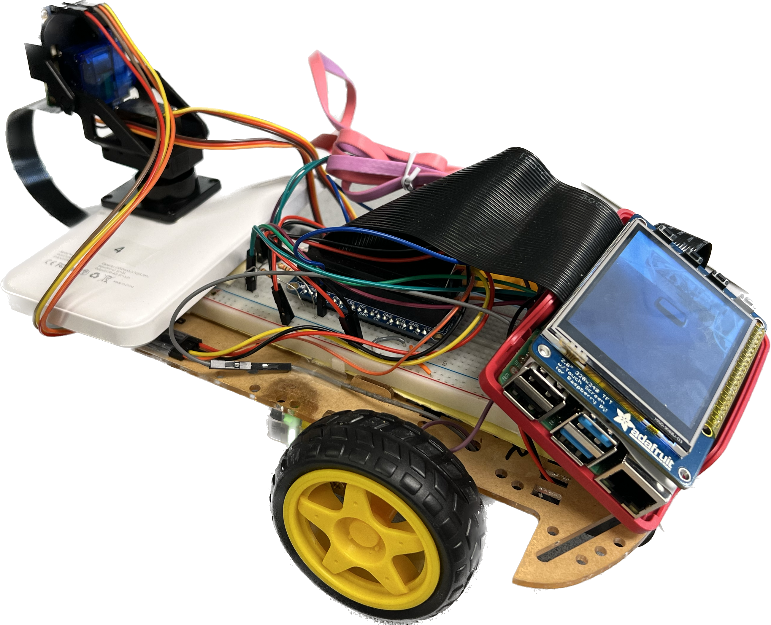
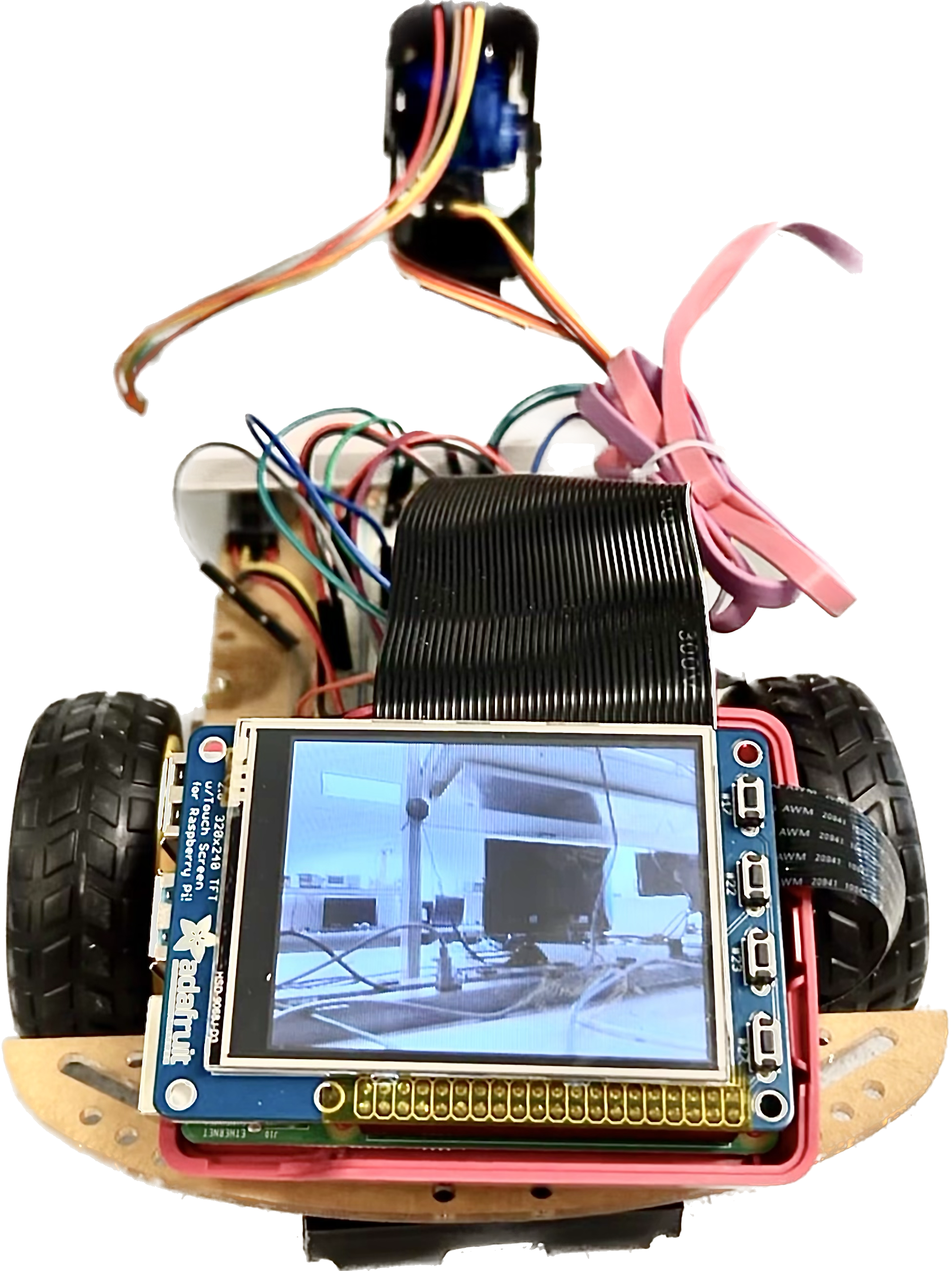
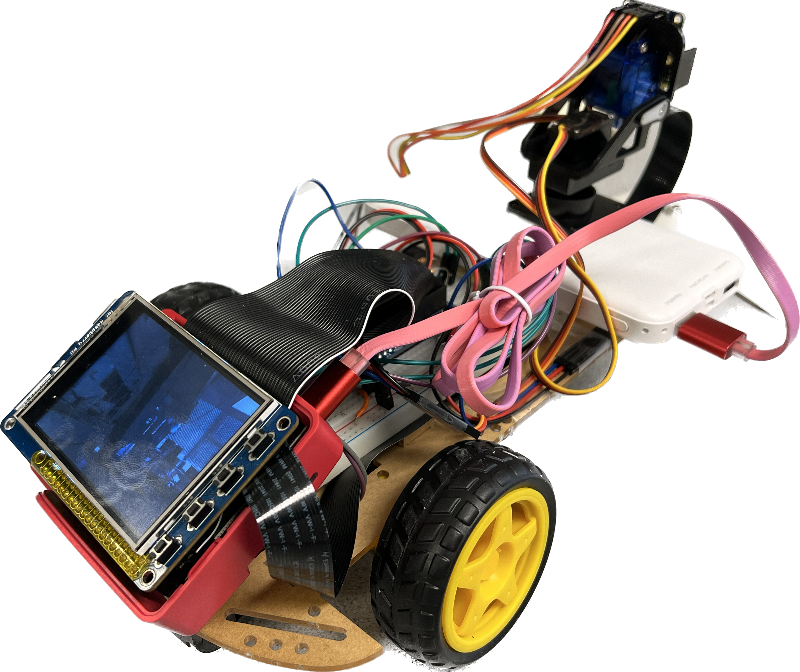
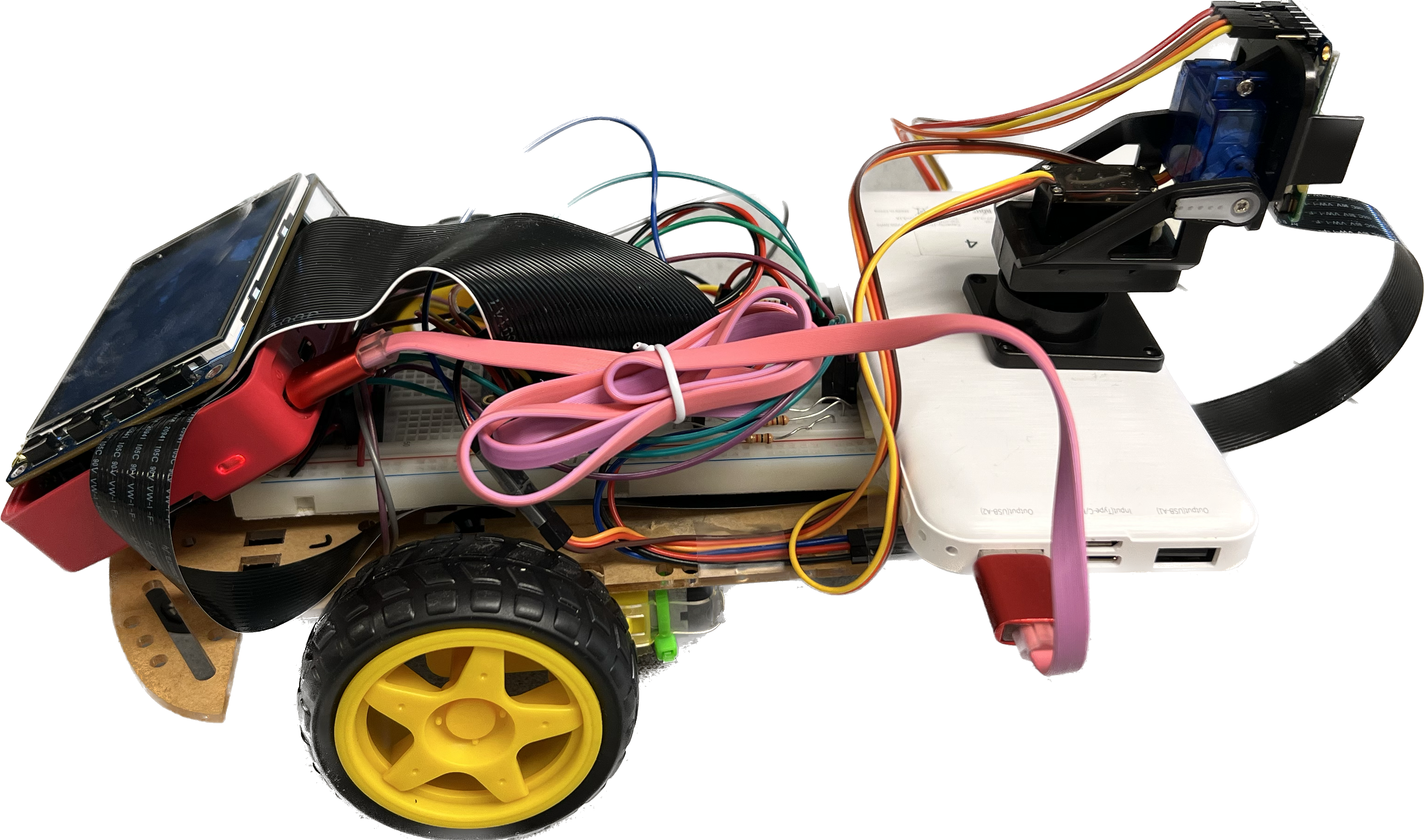
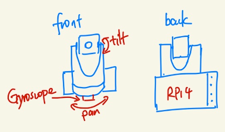
a.Hardware Assembly: The primary computing unit for our system is the Raspberry Pi 4 (RPi4), which hosts our software and interfaces with all other hardware components attached to the RPi4 is a 2.8-inch PiTFT touch screen, which serves as a local display and user interface. For image capturing and motion tracking, we utilized the Pi Camera v2 module. This camera, along with a BNO055 sensor, is mounted on a pan-tilt mechanism driven by two SG90 servo motors. The BNO055 sensor, a versatile device capable of measuring temperature, orientation, and calibration status, is crucial in our stabilization mode. The entire assembly is mounted on a robot car, which we controlled using a Sparkfun TB6612FNG dual-channel motor controller. This controller allows us to send precise signals to the DC motor of the car, enabling smooth and accurate movement.
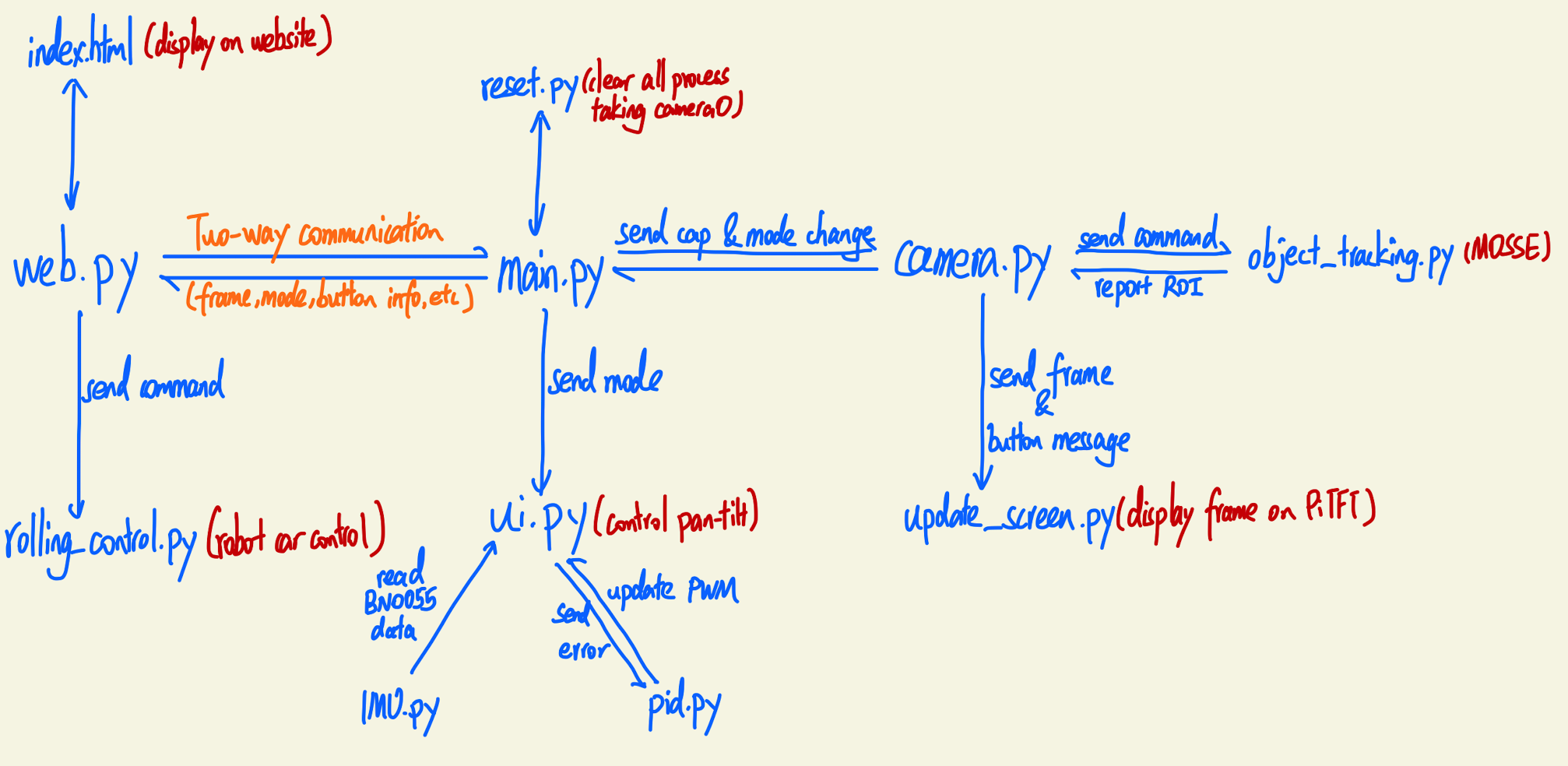
b.Software Integration: Our system comprises of nine Python scripts, each serving a specific purpose:
- main.py: This is the central script, orchestrating the various functionalities of our system. It controls the camera system and manages the different operating modes – manual control, object tracking, and stabilization. It also handles the synchronization between different processes and threads using locks and shared memory.
- camera.py: This class extends threading.Thread and controls the camera. It provides methods for object tracking, using the MOSSE algorithm, and displaying messages on the screen.
- imu.py: This code interacts with the BNO055 sensor, extracting data about temperature, orientation, and calibration status.
- object_tracking.py: This script implements the MOSSE tracking algorithm, providing a graphical interface for users to select a ROI in a video.
- pid.py: This class implements a Proportional-Integral-Derivative (PID) controller, a control loop mechanism used in industrial control systems.
- rolling_control.py: This script uses the Raspberry Pi's GPIO pins to control the robot car's movements.
- ui.py: This script handles different interaction modes with the device using Pygame and OpenCV libraries.
- update_screen.py: This class uses Pygame and OpenCV to create an interactive display on the PiTFT screen.
- web.py: This script sets up a Flask server for the remote control of the robot car via a webpage. The server runs on the Raspberry Pi and provides video feed, button controls, mode changes, and rolling controls.
The main.py script is synchronized with the web interface using two-way communication through a shared manager dictionary, ensuring that the system maintains a consistent state across different interfaces.
c.Software-Hardware Integration: The integration of the software with the hardware was a critical part of our project. The hardware components, such as the Pi Camera, BNO055 sensor, and the servo motors, were controlled by the software scripts. For instance, the object_tracking.py script used the Pi Camera to capture video frames, the imu.py script read data from the BNO055 sensor, and the rolling_control.py script controlled the robot car's movements.
Similarly, the output of the software, such as the object tracking results or the stabilization commands, affected the operation of the hardware. For example, the object tracking results were used to control the pan-tilt mechanism of the camera and the stabilization commands were used to adjust the robot car's movements. This integration was achieved through a combination of Python libraries, including multiprocessing, threading, and GPIO for Raspberry Pi. These libraries allowed the software to interface with the hardware components, control their operation, and react to their output.
Testing:
Testing was a crucial part of our project development to ensure that every step was implemented correctly and functioned as planned. Each component was tested individually, and then the entire system was evaluated as a whole to ascertain its overall reliability and efficiency.
1.Unit Testing: At the initial stage of the project, each Python script was tested individually. This unit testing allowed us to verify the functionality of each module and correct any bugs early in the development process. For instance, in camera.py, we confirmed that the camera was able to capture and process frames correctly. In imu.py, we verified the correct functioning of the BNO055 sensor, ensuring it could measure orientation. Similar testing was performed on all other scripts to validate their individual functions.
2.Integration Testing: Once the unit testing was complete and the individual modules were confirmed to be working correctly, we proceeded with the integration testing. This stage involved combining all the individual parts and testing them as a whole system. It helped us identify any inconsistencies or issues that arose when the different modules interacted with each other. For instance, we tested the synchronization between the main script and the web interface, ensuring that changes made through the web interface were accurately reflected in the local system, and vice versa. We also tested the overall functionality of the camera system in its different modes, checking that the system could seamlessly switch between manual control, object tracking, and stabilization modes.
3.System Testing: Finally, we performed comprehensive system testing to evaluate the performance of the entire system under real-world conditions. This involved testing the system both in handheld mode and as a remotely controlled robotic car. We checked the accuracy and responsiveness of the system in different situations, including variable lighting conditions, different object shapes and sizes for tracking, and various surface types and inclines for the car.
Throughout these testing stages, we applied a rigorous debugging process. Any issues identified were carefully analyzed, and corresponding solutions were implemented to improve the system's functionality. This iterative testing and debugging process was instrumental in ensuring the system's reliability and performance met our expectations. By performing rigorous testing at every stage of development, we were able to confirm that each component and the overall system performed as planned, ultimately achieving our project objectives.
Issues and Solutions:
During the course of this project, we encountered several challenges that required thoughtful problem-solving and innovative approaches. Each of these issues provided valuable learning experiences and opportunities for improving our design and implementation process.
1.Consolidating Screen Instances to Ensure Proper Message Display in Camera and User Interface Interaction: One of the challenges we faced was ensuring the proper display of messages in the camera and user interface (UI) interactions. Initially, there were discrepancies and inconsistencies in the way messages were displayed on the screen, leading to confusion and a less intuitive user experience. To resolve this, we consolidated all screen instances into a single, shared instance that could be accessed by all necessary modules. This ensured that all messages were accurately and consistently displayed across the camera and UI, enhancing the system's usability and user experience.
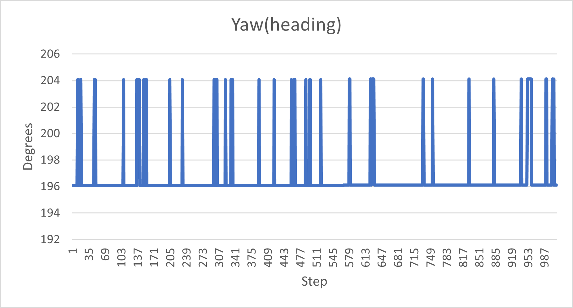
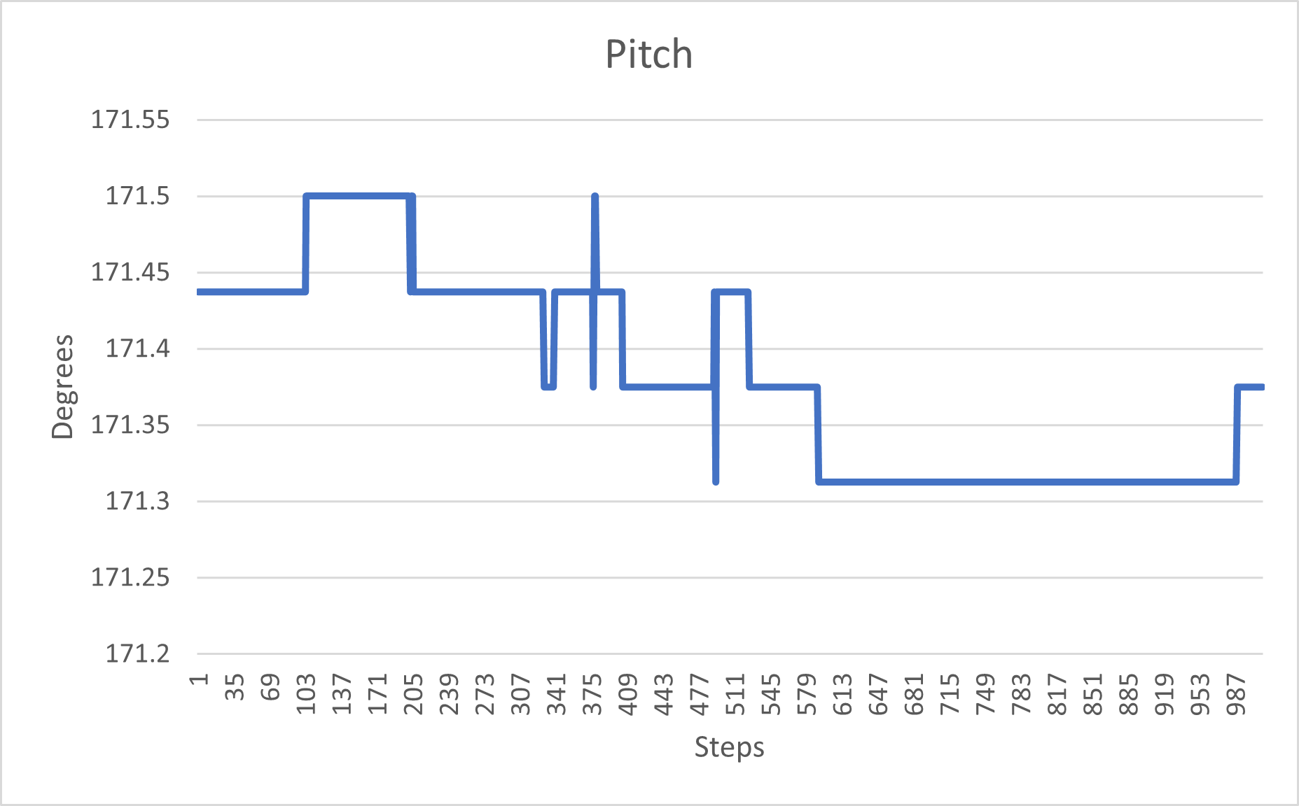
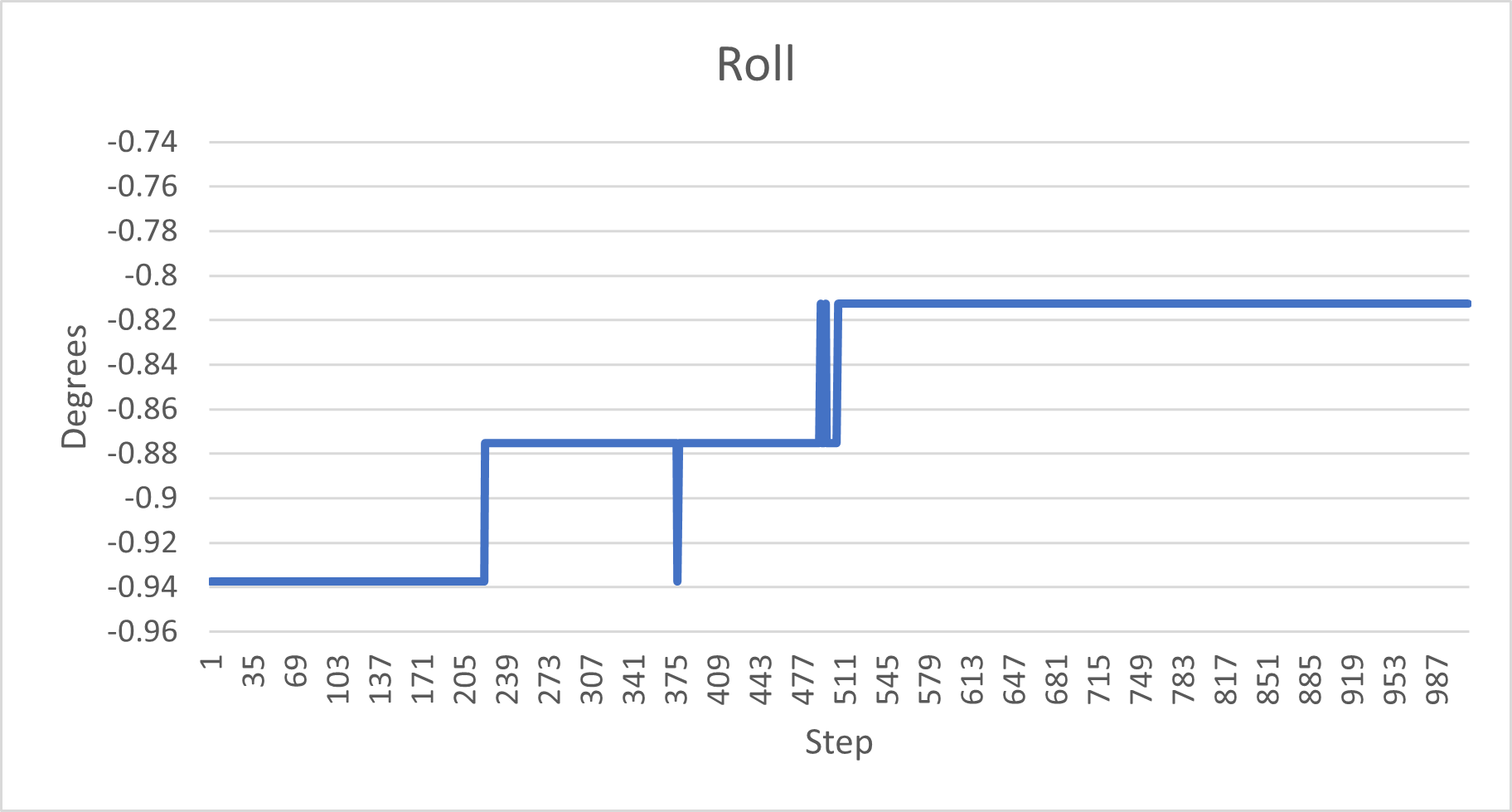
2.BNO055 Sensor Noise: A significant issue we encountered was the noise in the data readings from the BNO055 sensor. The sensor's readings were not stable for the pitch and yaw axes, which presented a challenge for the stabilization task. While we were unable to completely solve this issue due to hardware limitations, we implemented a workaround by focusing on the roll axis, where the sensor readings were more stable. This allowed us to still accomplish the stabilization task effectively, albeit with a narrower scope than initially planned.
3.Two-Way Communication: Ensuring stable, two-way, dynamic data sharing between the main script and the web interface was another challenge. It was crucial for the system's operation that any changes made via the web interface were accurately reflected in the system's local operations, and vice versa. We tackled this issue by implementing a shared manager dictionary, which facilitated the efficient and accurate sharing of data between the main script and the web interface. This ensured smooth, reliable two-way communication, enhancing the system's remote operability.
4.Camera Delay: The final issue we faced was a delay between the camera's frame capture and the robot's movement when the system was connected to WiFi for bi-directional frame sharing. The extent of this delay varied, sometimes minimal, but other times quite significant, causing a lag in the system's response to user inputs. This issue could potentially be resolved by using a dedicated hotspot for the system, which could provide a more stable and faster connection. However, due to limitations in our testing environment, we were unable to implement this solution during the project's timeframe.
Each of these challenges, whether fully resolved or mitigated through alternative strategies, contributed to the evolution of our project. They served as valuable learning experiences, reinforcing the importance of thorough testing and iterative development in creating a robust, effective system.
Results
The execution of our project led to fruitful outcomes, fulfilling our initial project goals while also exceeding them with the addition of challenging components not initially planned for. Our primary objective was to build a handheld camera system with object tracking, stabilization features, and a user-friendly interface, all of which we successfully achieved.
1.Object Tracking: In our final project demonstration, we showcased the camera's ability to select a region of interest (ROI) on the touchscreen and actively track and center this ROI.
2.Partial Camera Stabilization: Our camera system demonstrated efficient stabilization capabilities, albeit partially. It effectively stabilized unwanted movements on one axis, ensuring relatively smooth and steady footage. However, due to inherent limitations and noise in the BNO055 sensor readings, we could not fully implement stabilization across all axes as initially planned. This represents an area for potential future improvement in our system.
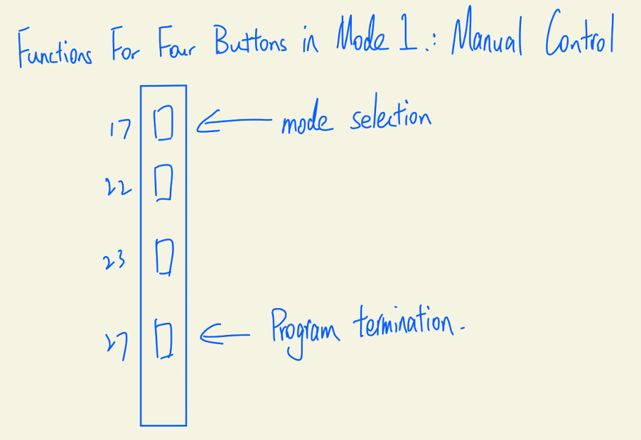
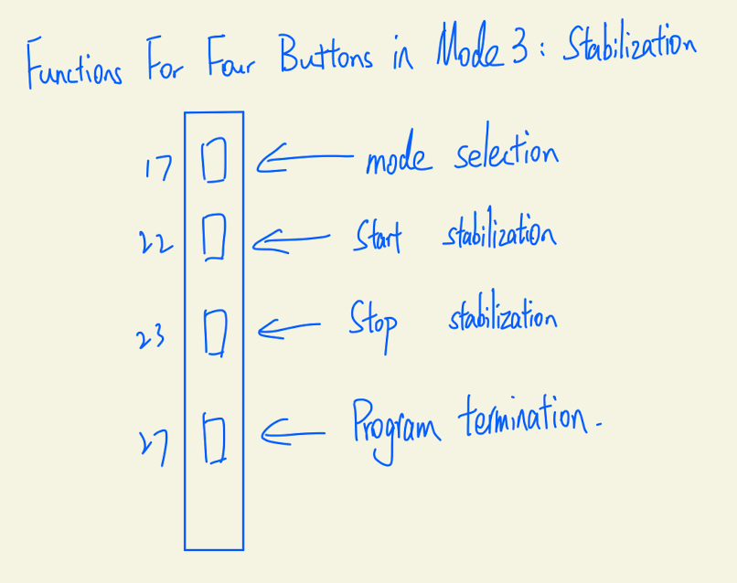
3.User Interface: Our user-friendly touchscreen interface, coupled with four physical buttons for mode selection, confirmation, recording, and program termination, was demonstrated to be intuitive and easy to operate.
4.Portability: The final prototype was compact, lightweight, and designed for handheld use, making it suitable for diverse applications. This was emphasized during the demonstration.
Beyond our original objectives, we ambitiously extended the project scope. We added a manual control mode to the camera system and integrated the setup onto a moving robot car. This addition increased the complexity of the project but ultimately broadened the system's functionality and versatility. Moreover, we developed a web interface for remote operation of the robot car, enabling two-way communication between the user and the system. Despite the ambitious nature of this feature, we successfully implemented it, enhancing the user experience and expanding the potential applications of our system.
In conclusion, our team met most of the goals outlined in the original project description, and we successfully tackled additional challenges we set for ourselves. Despite the partial fulfillment of the stabilization task due to sensor limitations, the resulting system is more robust and versatile than initially planned, making us very proud of the achieved results.
Conclusion
Our project resulted in the development of a versatile and robust handheld camera system that can also be operated remotely via a web interface. This system demonstrated its capabilities in object tracking, partial stabilization, and user interaction, fulfilling most of the project's initial objectives.
The most significant achievement of our project was the successful implementation of the object tracking feature. Our system could identify and track a region of interest (ROI) on the touchscreen effectively, maintaining the ROI at the center of the frame despite user movement or rotation. This achievement was a cornerstone of our project, demonstrating the potential of our system in various applications that require active tracking. The introduction of a manual control mode and the integration of the camera system onto a robot car were additional successes. These features were not part of our initial objectives but were ambitious extensions we set for ourselves. The successful implementation of these features enhanced the functionality and versatility of our system, allowing for a more diverse range of applications. Moreover, we successfully developed a web interface for remote operation of the robot car. The interface facilitated two-way communication between the user and the system, further enhancing the user experience and the system's potential.
However, the project encountered a major challenge regarding the stabilization feature. Although we intended to implement stabilization across all axes, the limitations and noise inherent in the BNO055 sensor readings meant we could only achieve stabilization along one axis. This issue was a key learning point in our project, underscoring the importance of hardware reliability in achieving desired software functionality.
In summary, our project achieved most of its goals, resulting in a multi-functional camera system capable of object tracking, partial stabilization, and user-friendly interaction. Despite the encountered challenges, the team successfully navigated these issues to deliver a product that not only met the initial project objectives but also surpassed additional self-imposed challenges. These experiences and learnings will undoubtedly guide us in future endeavors.
Future Work
Given more time to work on this project, there are several areas of exploration and enhancement that we would like to pursue to further improve the capabilities of our handheld and remote-controlled camera system:
1.Enhanced Stabilization: The issue of achieving stabilization only along one axis due to limitations of the BNO055 sensor was a significant challenge we faced. In the future, we would look into using a more reliable and accurate sensor or a combination of sensors for enhanced multi-axis stabilization. The goal would be to create a fully stabilized camera system, providing even smoother footage regardless of the user's movement or rotation.
2.Advanced Object Tracking: While the current system performs adequately in tracking objects, more advanced algorithms could be implemented to improve accuracy and robustness, particularly in challenging environments. Techniques such as deep learning-based object tracking could offer improved performance and adaptability.
3.Autonomous Navigation: With the system already mounted on a robotic car, another interesting extension would be the addition of autonomous navigation capabilities. This could be achieved by integrating obstacle detection and avoidance mechanisms, thereby enabling the robot to navigate independently while continuing its object tracking and stabilization operations.
4.Improved User Interface: We could also explore improvements in the user interface, both on the device itself and the web interface. This could include more intuitive controls, additional features, and better feedback mechanisms for the user.
5.Real-time Video Processing: The delay issue experienced during the project could be addressed by exploring more efficient video processing and transmission methods, potentially using more powerful hardware or optimizing the software for better performance.
The above enhancements would not only address some of the limitations encountered in the current project but also push the boundaries of what our system can achieve, making it even more versatile and useful in a wide array of applications.
Work Distribution
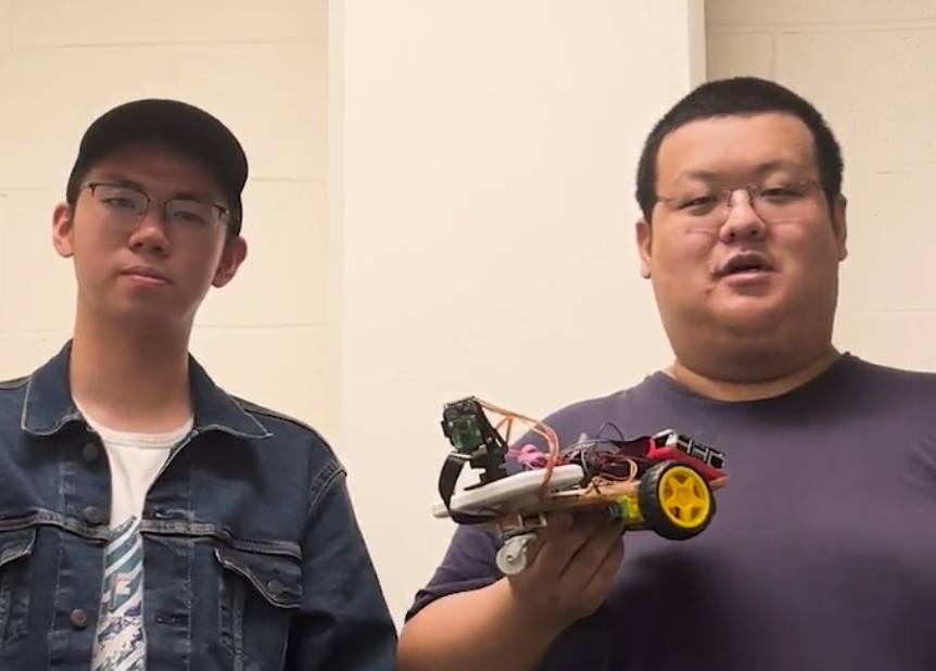
Project group picture
Zehao Li
zl823@cornell.edu
- Involved in the software development aspect of the project.
- Designed the object tracking and stabilization modules to facilitate the camera's various modes.
- Coordinated hardware and software integration to ensure efficient and harmonious performance of the camera system.
Jinhong Yu
jy773@cornell.edu
- Assembled the hardware components, ensuring their correct integration and functionality.
- Built a user-friendly Flask web interface to facilitate remote control of the camera system.
- Handled motor control to manipulate the robot car's movement.
- Conducted testing of the system and coming up with efficient solutions.
Budget
- Raspberry Pi 4 with 2.8 inch PiTFT Screen (Borrow from Professor)
- Raspberry Pi Camera Module 2 (Borrow from Professor)
- Pan-Tilt Camera Mount (Borrow from Professor)
- 2x SG90s motors (Borrow from Professor)
- Robot Car (Borrow from Professor)(Same Device in lab3)
- Adafruit BNO055 Absolute Orientation Sensor ($29.95)
Acknowledgements and References
We would like to express our sincere gratitude to our professor, Joe Skovira, whose extensive knowledge, insight, and unwavering support played an instrumental role in the successful completion of this project. Your continuous guidance, expertise, and support throughout this journey have been truly invaluable. We sincerely appreciate your readiness to answer our questions, help troubleshoot issues, and offer potential solutions. Moreover, the way you fostered a collaborative atmosphere by connecting us with other teams greatly enriched our learning experience and allowed us to gain broader perspectives. We would also like to express our heartfelt thanks to our teaching assistants. Your tireless dedication and commitment to our success did not go unnoticed. Throughout the lab sessions, you consistently monitored the progress of our project, offering insightful advice and constructive feedback that helped us improve and refine our work.
References
1.Python Libraries: Several open-source Python libraries were used in the development of this project, including OpenCV, Pygame, Flask, multiprocessing, threading, and RPi.GPIO. These libraries' official documentation were invaluable resources in understanding and implementing the required functionalities.
2.Raspberry Pi Resources: The Raspberry Pi Foundation's official documentation is essential in understanding how to properly utilize and interface with the Raspberry Pi 4 and its peripherals.
3.Adafruit Hardware: Adafruit's guides and tutorials on using the PiTFT display and the BNO055 sensor were useful references.
4.SparkFun Electronics: The documentation and guides from SparkFun were instrumental in learning how to use the TB6612FNG dual motor driver.
5.MOSSE: To implement the MOSSE object tracking, we referred to the original paper:
6.ChatGPT: In the course of this project, we utilized the capabilities of ChatGPT, an advanced language model developed by OpenAI, to debug our code, generate ideas, and facilitate our project's successful completion. The intelligent text generation and problem-solving abilities of ChatGPT were invaluable in enhancing our productivity and achieving our objectives.